Maya Research 3D:
What is 3D Modelling:
- 3D modelling is the use of software’s to create a virtual three-dimensional model of some physical object. 3D modelling is used in a variety of industries, including Virtual reality, Video games, 3D printing, Marketing, TV and motion pictures, scientific and medical imaging and computer-aided design and manufacturing CAD/CAM. 3D modelling software generates a model through a variety of tools and approaches including:
- simple polygons
- 3D primitives — simple polygon-based shapes such as pyramids, cubes, spheres, cylinders, and cones.
- spline curves.
- NURBS (non-uniform rational b-spline) — smooth shapes defined by bezel curves, which are relatively computationally complex


- In art for video games and motion picture effects, a model might start as rough using polygon primitives or NURBS, or even a design made by following contours on multiple 2D isometric views. If the model is to be animated, careful consideration of the arrangement of continuous edge loops must be maintained in the model’s polygons around areas of deformation such as joints. A model that looks good and detailed will be able to fold fast once a model is adequately built, an artist might arrange the coordinates of the model to match its 2D textures in a process called UV mapping, a process that is similar to tailoring but with a computer mouse. Areas that require more detail are given more space on the UV map. This can be done either using a repeating texture such as a checkerboard as a placeholder or by using an existing texture.
-
How is modelling for games different from modelling for films or any other medium:
One difference between modelling for games is that in films there is no limit to the use of polygons that can be in any model. For movies, the only constraint you have is time, movies have deadlines which must be met. Although in movies you’ve got a free range to use however many polygons it takes to get the model to look good on screen because at the end that’s what matters
 However, for games, its very different, Games are rendered in real-time in front of the player in order for the game to run at a constant frame rate and maintain throughout the gameplay. 3D models must be created at a level that’s not taxing on the game engine. As you’re playing a game there can be thousands of different assets all being rendered at one time on the screen, taking a lot of processing power.
-
Hard Surface / Organic Modelling:
In 3D modelling, there are two categories for modelling, Hard surface, and Organic modelling. Hard surface means models that are machined or man-made, these include things like a computer, phones, weapons as examples.


- Organic modeling is models which are organic like trees, grass, animals and even people (Humans). Organic models have smoother flowing shapes and very few hard edges whereas Hard surface is the exact opposite with sharp edges and angular shapes.


- However, when comes it comes to terms of whether an object is defined as hard surface or organic is when it’s animated. If the asset becomes animated then its considered organic, but if its a static object then its considered hard surface. Although when it comes to differentiating whether an object is hard surface or organic depends on its topology, the characteristics of the mesh can determine whether or not it’s hard surface or organic. If a model has flowing curves where the shapes smoothly transition into another will mean it’s organic. For example, a sports car is man-made making it hard surface by definition, but yet it consists of extremely smooth and flowing curves.

-
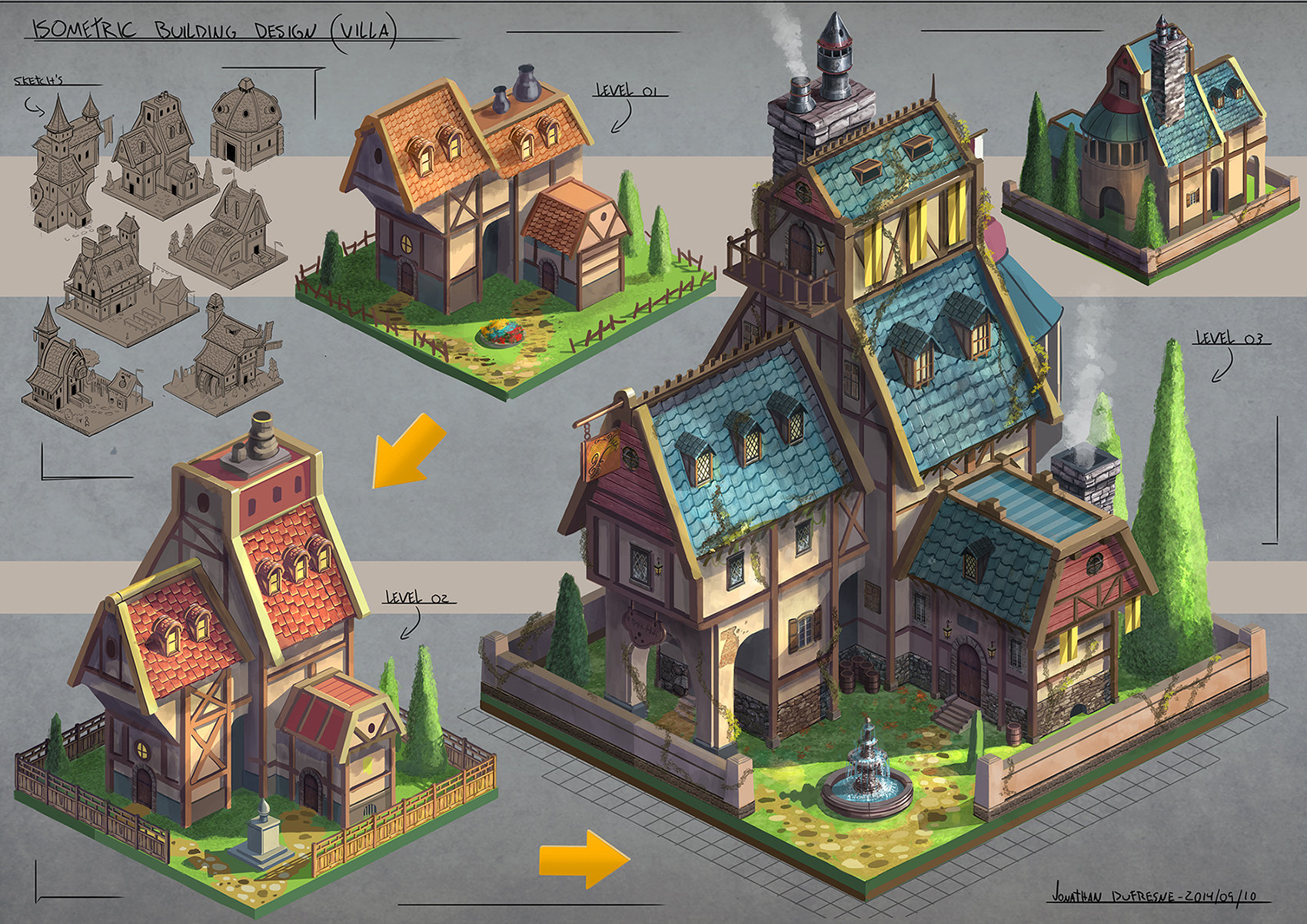
Environment Modelling (focus on buildings):
Environment modelling is the process of creating a visual 3D landscape or Building using a 3D software such as Maya, 3ds Max, and Blender. With the environment, modelling requires more time as it requires extra detail in modelling the world and buildings of your game. The basics of creating a 3D Building is making a base for the layout of the building, Then make simple shapes of the building design so you know where which piece goes where. For example, most buildings are simple squares.

Then when you have your base, you begin to start getting detailed with the overall layout. This is when 3D sculpting comes in, 3D sculpting software like Mudbox and ZBrush are commonly used for modelling characters and objects (Organic modelling). However, they are vital in environment modelling too as they create realistic environments to immerse the player.


-
Modular modelling / Unique Modelling:
The term “modular modelling” usually refers to the use of interchangeable components (or modules) in a model. The component may be a single equation, but typically it is a large component. Modular modelling is comparable to “LEGO” as the process is using similar asserts to create structures like buildings. The asserts are repeatable which makes modelling easier and efficient. for example the image below is of a modelled apartment building, however it has been separated into individual models to help construct the whole building.

“Unique modelling” is the direct opposite of “Modular modelling”, the model itself is unique from other models meaning that it cannot be repeated. Usually these models consist of props primarily since they are asserts meant to improve an environments immersion. For example the image below is of a retro radio, as you can see the model is unique in its style and texture.

-
High Poly Modelling / Low Polly Modelling:
High poly modelling is when a model’s level of detail needs to be highly detailed, such as when the model is used in close-ups. High poly models are also used to generate displacement and normal maps to use on lower-resolution models. This technique is used to add needed detail without the issues that come with high-resolution models.

Low poly modelling is a very low detailed model with fewer polygons and geometry. It places a very low load on the system on which it is being created or rendered. The number of triangles needed to consider something low poly is based on the rendering platform and increases as the technology improves.
-
Different modelling software:
There are many different modelling software’s available for anyone to use and learn. Here are the top 5 modelling software’s:
- Autodesk Maya
- Autodesk 3Ds Max
- Blender
- Zbrush
- SketchUp
All these modelling software’s are equally good but serve different uses. For example “Sketch up” is generally used for modelling buildings for architecture concepts. “Maya” and “3Ds Max” are similar since they are both used for modelling in different fields like video games, films and architecture, although there are debates to which software is better than the other.
-
Modelling Terminology:
1. NURBS: stands for Non-Uniform Rational Basis Spline. A NURBS model is a mathematical modelling type commonly used to generate curves and surfaces. The main advantages of this modelling technique are the great flexibility and precision you have in generating your shapes.
In contrast to Polygon Modelling, curve are created with a tool that works very similar to the pen tool in MS paint or adobe Illustrator. The curve is drawn in a 3D space, and edited by moving a series of handles called CVS or Control vertices.

2. Polygon Modeling: A good way to introduce Polygon models is to compare them with NURBS models: NURBS is a mathematical model whereas Polygon models (Also referred to as Meshes) are a collection of vertices, edges and faces that define the model, which allows for easy and precise editing of parts of your object. By changing the coordinates of one or several vertices, you can change the shape of the model.
Faces: A face is the most basic part of a 3D polygon. When three or more edges are connected together, the faces is what fills in the empty space between the edges and make up what is visible on the polygon mesh.

Edges: An edge is another component of a polygon. Edges help define the shape of the models, but they can also be used to transform them. An edge is defined by two vertices at their end points.

Vertices: A vertex is the smallest component of a polygon model. It is simply a point in a three-dimensional space. By connecting multiple vertices with edges you can create polygon. These points can be manipulated to create the desired shape.

Maya Research 2D:
-
Research – What are UV’s:
UV Mapping is a technique to apply 2D texture on 3D object. “U” and “V” are the axis names of 2D Texture while “X”, “Y” and “Z” are used for 3D Model Objects. It will a wrap a 2D image around 3D Object. UV Mapping spread polygons of 3D model on to a 2D plane in order to Map texture on it.


-
Research – 0-1 UV Space:
UV space is flat, with U being left to right V being up and down. The lower left corner of the space is 0,0 going to 1 at the top and right edge. A coordinate [0,0] corresponds the lower left corner, and [1,1] is the upper right corner (depending the render engine/software).

-
Research – Working outside the UV space
If you work outside the UV grid the size of the texture will change inverse proportionally. If you make the UVs larger the texture will get smaller and start repeating itself.

-
Research – UV Software and methods
UVing software such as ZBrush, 3DX MAX and Maya all have UVing software included in their program. Some methods of UVing are unique in these software’s, for example on Maya there is “Automatic Unwrapping” which automatically unwraps your object by attempting to find the best UV placement by simultaneously projecting from multiple planes. This method of UV mapping is useful on more complex shapes where the basic planar, cylindrical, or spherical projections do not produce UVs that are useful, especially on components that project outwards or are hollow in nature.

Another method is “Planar mapping”. This method is mapping projects UVs onto mesh through a plane. This projection is best for objects that are relatively flat, or at least are completely visible from one camera angle.

Planar mapping typically gives overlapping UV shells. The UV shells may be perfectly superimposed and look like a single UV shell. You should use UV Layout after mapping to separate overlapping UVs.
-
Research – How to UV with Maya
As stated earlier Maya has different methods of UVing objects depending on its look and use. The different methods are:
- Automatic UV mapping
- Planar UV mapping
- Cylindrical UV mapping
- Spherical UV mapping
- User-defined UV mapping
Each UV mapping method produces UV texture coordinates for the surface mesh by projecting them onto the surface mesh based on its inherent projection method. As a result, the UV texture coordinates have initial 2D spatial correlation to the vertex information in the 3D world space coordinate system. It is this correlation between the texture map and the surface mesh via the UVs that positions the texture on the surface.
-
Research – Texture Maps
Texture mapping is a method for defining high frequency detail, surface texture, or colour information on a 3D model. (Texture and materials are render nodes. Render node attributes describe how the node appears and behaves) The attributes to which the texture is connected determines how the texture is used and how it affects the final results.

-
Research – Transfer Maps
Transfer maps allow you to take one model and make another model look exactly the same through normal maps, displacement maps and bump maps. Transfer maps allow both the target mesh (this is the mesh that the transfer map will apply the normal maps from) to have completely different geometry, different UV maps, and different polygon resolution. The whole point of this is to make our low polygon torus without increasing the low polygons geometry.

1. Maya Introduction:
Maya User Interface
This is the Maya user interface. The tutorial video covered what each tool does and how to use them accordingly. Here is what each individual tool does:
- Menu Sets: This tool divides the different menu types into categories: Modelling, Rigging, Animation, FX, and Rendering. The first seven menus on the main menu are always available, but the remaining menus change depending on the menus set you’re to choose.
- Top Menus: The menus contain tools and actions used for working in your scene. The main menu is located at the top of the Maya window. There are individual menus for the panels and option windows. Also, you can access the menus in the main menu in the hotbox, which you can open by holding down the spacebar in a view panel.
- Status Line: The status line contains icons for commonly-used commands, such as File > Save, as well as icons for setting up object selection, snapping, rendering, and more. There is also a quick Selection field available for you to set up for numeric input.
- Shelf: The Shelf contains tabs that represent each menu set. Each tab contains icons that represent the most commonly-used commands for each set. The real use of shelves is the ability to create custom shelves, and then make tools or commands that are quickly from with a single click.
- Sidebar Icons: These icons at the right end of the status line open up tools that you will use frequently. From left to right, you click each icon to toggle opening and closing the Modelling Toolkit, the HumanIK window, the Attribute Editor, the Tool Setting, and the Channel Box (which is open by default and shown).
- Channel Box: The Channel Box lets you edit attributes and key values for selected objects. The transform attributes are shown by default, but you can change which attributes are displayed.
- Tool Settings: The Tool Settings panel displays many working options for the currently selected tool. For example, you can set many options for the select, Move, Rotate and Scale tools in this panel.
- Attribute Editor: The Attribute Editor list attributes on the selected object. Tabs across the top of the Attribute Editor let you select nodes connected to the shown node.
- Tool Box: The Tool Box contains tools that you use all the time to select and transform objects in your scene. Use the “QWERTY” hotkeys to use the Select tool (Q), Move tool (W), Rotate tool (E), Scale tool (R), and Show Manipulators (T), as well as access the last tool used (Y) in the scene.
- Time Slider: The Time Slider shows you the time range that is available as defined by the range slider, below. The slider also displays the current time and the keys on selected objects or characters. You can drag the red playback cursor in it to “scrub” through animation, or use the playback controls at right end.
- Range Slider: The Range Slider lets you set the start and end time of the scene’s animation and a playback range, such as if you want to focus on a smaller portion of the whole animation.
- Command Line: The Command Line has an area to the left for inputting single MEL commands and an area to the right for feedback.
- Help Line: The Help Line gives a short description of tools and menus items as you scroll over them in the UI. This bar also prompts you with the steps required to complete a certain tool or workflow.
2. Maya Navigation:


Tap Making Tutorial:
10 Building Design Choices:
Building 1:

I choose this building from a “Skyrim” building concept art. I like the design of the slope of the roof as well as the stone hedges holding the building together, it makes for a good fantasy style building.
Building 2:
I like this building from the game “Defiance” as the building is covered with scrap sheets, wooden planks, and broken wooden walls.
Building 3:

This Building concept from “Bioshock Infinite” is has a simple building design but what i like about it is the texture and detail put into the individual assets.
Building 4:
These concept buildings from “Artstation” have various building designs that offer different concepts and different degrees of detail. Some of these would be a good start for 3D modeling.
Building 5:

This is a concept building for a Tudor house, The overall layout is quite simple in terms of structure but the texturing is very detailed so it would take awhile to texture this model.
Building 6:

This is a concept of an Asian style fortress from “DeviantArt” by Ortsmor, I choose this because the building has a simple texture pattern repeating itself along the building. As well as the overall building layout which is unique to over buildings.
Building 7:

This building from “Assassins Creed Rogue” is a good start to 3D modeling a building because it can be cut up to 3 sections of shapes making it easier to make the base building, and just like the previous building, the textures repeat itself along the whole building making it quicker to texture the building.
Building 8:

These building concepts are from “World of Warcraft”. What I like about this is that the concept has divided the building in two making it easier to see interior design. I also like the wood textures they have a weathered look that stands out.
Building 9:
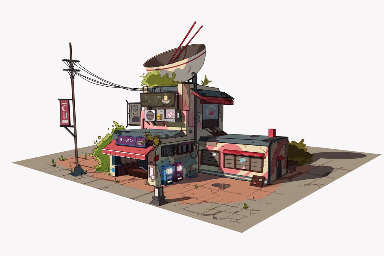
I choose this building concept by Janice Chu because I like the theme and art style. The theme is a Japanese style noodle bar, the art style is anime orientated with no abstract or exaggerated shapes making way for bright, colourful details and simple shapes.
Building 10:
I choose this final building from “Pinterest” because the layout really intrigued me. This design is placed in a disorganized order making it look complicated visually but easy to identify the different shapes of the building e.g. Rectangle, Triangles.
The 5:


Out of the 10 Buildings designs I have collected, I have chosen 5 as a starter of what I could use for my final piece judging by its design pros and cons.
1.
The first building looks simple in terms of base and shape as the building itself is just rectangles, however there are many asserts and multiple side objects around or on the building which prove to look extensive to make due to limited time
2. 
The second building looks complex by first look but it can be dissected into segments to help create individual sectors. Although there are many patterns which are mostly unique to each other.
3. 
The third building has a basic building shape of a normal cube, what makes the building unique is the detail of the pipes, windows and boarded up wood. However there are two buildings detached along a clothing line, which makes work longer as both separate buildings have to be detailed individually.
4. 
The fourth building has a good building layout with limited complex detail needed, however the simple design layout and less detail make the building quite plane.
5. 
The last building is a fortress design so there is a tower and a wall which repeats itself across with a gate entrance, but the fortress design has slanted edges across the whole thing making it time consuming.
The 3:


These are the final 3 that i think are potential for my final choice. Building 1 is good for starting a base and detailed, but however there is 2 parts to the building. Building 2 is simple and straight forward but i feel could include additional detail to the design layout. Building 3 can be cut into segments to help make it easier to make but the detail is “organic” because each detail is random and cannot be repeated.
Final Choice:

I have chosen this building as the design and layout is relatively simple. The building can be cut into segments to help decide on the geometry of the building in areas which aren’t visible from the base image.

I have separated the building into 7 different parts to help visuals on Maya what the building would look like on multiple angles. I have also collected details of the building that are unique and that could also be used as a repetitive asset.
Here is a Video on YouTube of my Building process. Its shows from beginning to end of how I made my Building.

This is the finished look of my building fully textured. My complaints are that for the railing on the roof, I could not find a method of removing the white overlay. The railing is meant to be clear so you can see through the hole. However despite that, I am extremely proud of my final building design overall.
